- 您现在的位置:买卖IC网 > Sheet目录364 > SST25VF064C-80-4I-Q2AE-T (Microchip Technology)IC FLASH SER 64M DUAL I/O 8WSON
64 Mbit SPI Serial Dual I/O Flash
A Microchip Technology Company
SST25VF064C
Data Sheet
Security ID
SST25VF064C offers a 256-bit Security ID (Sec ID) feature. The Security ID space is divided into two
parts – one factory-programmed, 64-bit segment and one user-programmable 192-bit segment. The
factory-programmed segment is programmed at SST with a unique number and cannot be changed.
The user-programmable segment is left unprogrammed for the customer to program as desired.
Use the Program SID command to program the Security ID using the address shown in Table 7. Once
programmed, the Security ID can be locked using the Lockout SID command. This prevents any future
write to the Security ID.
The factory-programmed portion of the Security ID can never be programmed, and none of the Secu-
rity ID can be erased.
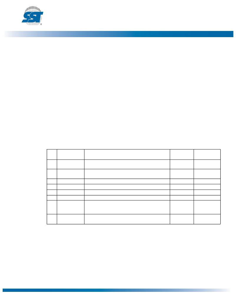
Status Register
The software status register provides status on whether the flash memory array is available for any
Read or Write operation, whether the device is Write enabled, and the state of the Memory Write pro-
tection. During an internal Erase or Program operation, the status register may be read only to deter-
mine the completion of an operation in progress. Table 4 describes the function of each bit in the
software status register.
Table 4: Status Register
Default at
Bit
0
Name
BUSY
Function
1 = Internal Write operation is in progress
Power-up
0
Read/Write
R
0 = No internal Write operation is in progress
1
WEL
1 = Device is memory Write enabled
0
R
0 = Device is not memory Write enabled
2
3
4
5
6
BP0
BP1
BP2
BP3
SEC 1
Indicate current level of block write protection (See Table 5)
Indicate current level of block write protection (See Table 5)
Indicate current level of block write protection (See Table 5)
Indicate current level of block write protection (See Table 5)
Security ID status
1
1
1
1
0 1
R/W
R/W
R/W
R/W
R
1 = Security ID space locked
0 = Security ID space not locked
7
BPL
1 = BP3, BP2, BP1, BP0 are read-only bits
0
R/W
0 = BP3, BP2, BP1, BP0 are readable/writable
T4.0 25036
1. The Security ID status will always be ‘1’ at power-up after a successful execution of the Lockout SID instruction; other-
wise, the default at power up is ‘0’.
?2011 Silicon Storage Technology, Inc.
8
DS25036A
06/11
发布紧急采购,3分钟左右您将得到回复。
相关PDF资料
SST25VF080B-80-4I-QAE-T
IC FLASH SER 8MB 50MHZ SPI 8WSON
SST25VF512-20-4C-SAE-T
IC FLASH SER 512K 20MHZ 8SOIC
SST25VF512A-33-4I-QAE-T
IC FLASH SER 512KB 33MHZ 8WSON
SST25WF040-40-5I-QAE-T
IC FLASH SER 4MB 40MHZ SPI 8WSON
SST25WF080-75-4I-ZAE
IC FLSH SER 8MB 75MHZ SPI 8CSP
SST26VF032A-80-5I-S2AE
IC FLASH 32MBIT 8SOIC
SST38VF6402-90-5I-B3KE-T
IC FLASH MPF 64MBIT 90NS 48TFBGA
SST39LF802C-55-4C-MAQE-T
IC FLASH MPF 8MBIT 48-WFBGA
相关代理商/技术参数
SST25VF064C-80-4I-Q2CE
制造商:SST 制造商全称:Silicon Storage Technology, Inc 功能描述:64 Mbit SPI Serial Dual I/O Flash
SST25VF064C804IS3AE
制造商:Microchip Technology Inc 功能描述:
SST25VF064C-80-4I-S3AE
功能描述:闪存 64M (8Mx8) 80MHz Industrial Temp RoHS:否 制造商:ON Semiconductor 数据总线宽度:1 bit 存储类型:Flash 存储容量:2 MB 结构:256 K x 8 定时类型: 接口类型:SPI 访问时间: 电源电压-最大:3.6 V 电源电压-最小:2.3 V 最大工作电流:15 mA 工作温度:- 40 C to + 85 C 安装风格:SMD/SMT 封装 / 箱体: 封装:Reel
SST25VF064C-80-4I-S3AE_
制造商:Microchip Technology Inc 功能描述:
SST25VF064C-80-4I-S3AE-T
功能描述:闪存 2.7V to 3.6V 64Mbit SPI Serial 闪存 RoHS:否 制造商:ON Semiconductor 数据总线宽度:1 bit 存储类型:Flash 存储容量:2 MB 结构:256 K x 8 定时类型: 接口类型:SPI 访问时间: 电源电压-最大:3.6 V 电源电压-最小:2.3 V 最大工作电流:15 mA 工作温度:- 40 C to + 85 C 安装风格:SMD/SMT 封装 / 箱体: 封装:Reel
SST25VF064C-80-4I-S3CE
制造商:SST 制造商全称:Silicon Storage Technology, Inc 功能描述:64 Mbit SPI Serial Dual I/O Flash
SST25VF064C-80-4I-SAE
制造商:SST 制造商全称:Silicon Storage Technology, Inc 功能描述:64 Mbit SPI Serial Dual I/O Flash
SST25VF064C804ISCE
制造商:Microchip Technology Inc 功能描述:
